
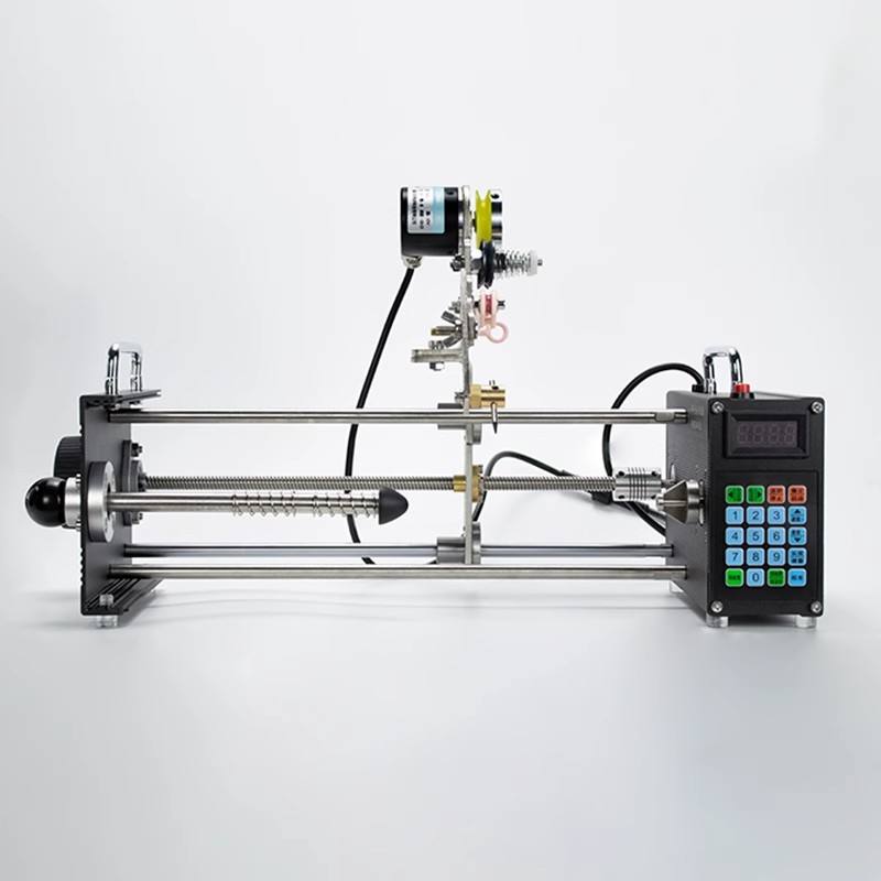
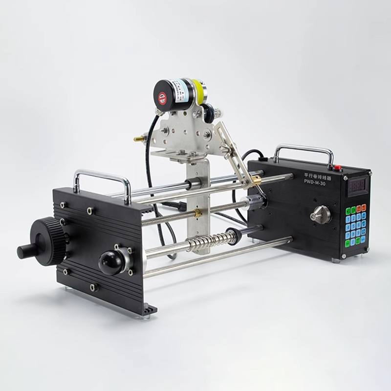
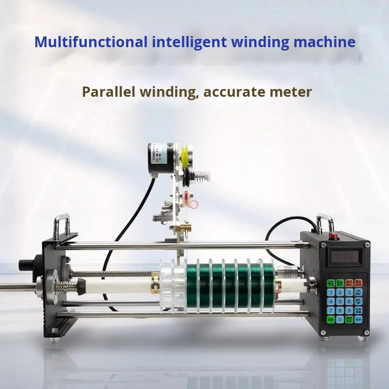
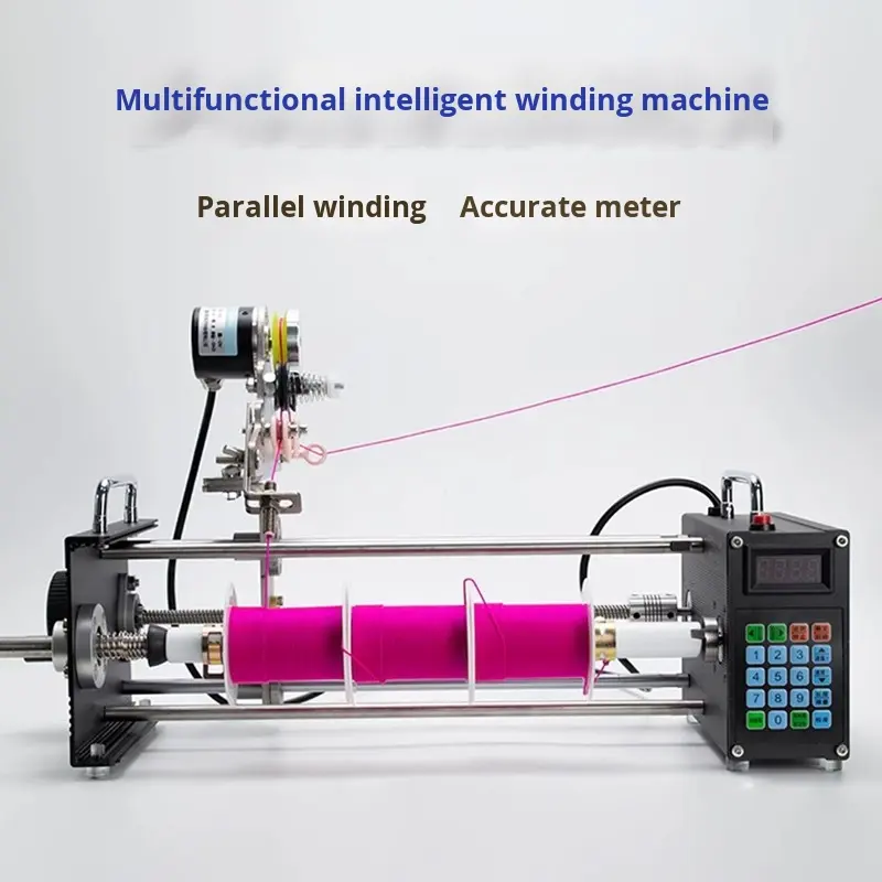
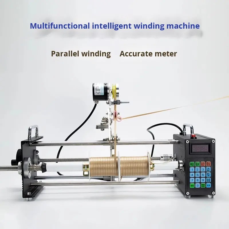
The CNC meter counting winding machine combines a documented metering function with parallel winding, touchscreen operation, a ceramic wire-contact path and resistance-triggered emergency protection. Model PWD-M-30 must be configured around the buyer’s actual fishing line or approved material, supply package and target wound product.
CNC Meter Counting Winding Machine Specifications
- Model: PWD-M-30
- Machine weight: 3.5 kg
- Machine dimensions: 700 × 260 × 300 mm
- Core component: motor
- Control: touchscreen intelligent operating system
- Winding function: parallel winding arrangement
- Wire contact: ceramic contact component
- Motion behavior: S-shaped acceleration and deceleration
- Protection: emergency stop when resistance reaches the configured threshold
- Configuration: customizable for the approved application
These values describe the verified source configuration. Metering method, usable material range, tooling, winding program, electrical scope and acceptance result must be confirmed for the final quoted machine.
Define What Meter Counting Means
A useful project begins by defining the controlled quantity. “Meter counting” may describe line length, while another application may focus on turns, spool fill or a related production value. The website name does not establish the buyer’s tolerance or inspection method.
State the target length or count, allowable variation and how the finished package will be checked. Mark the start and finish condition. If the line stretches, slips or changes length under tension, define the material condition during measurement. The CNC meter counting winding machine should be tested using the same definition that will be used for acceptance.
Metering performance depends on the line, contact path, feed resistance, acceleration, winding geometry and inspection method. A screen value is a process setting, not automatically the same as the measured finished result. BOYAN will confirm a project-specific result only after reviewing the application and trial method.
During development, record several consecutive samples. Identify the program, material batch, supply package, target setting and measured result. This provides evidence of the approved process and helps distinguish normal variation from a setup problem.
Parallel Winding and Fishing Line Separation
The documented parallel winding function is intended to support even, organized line placement. For fishing line or another approved material, the final result depends on the incoming path, guide, contact component, spool geometry and program.
Provide the number of lines or strands, their required relationship and the target wound width. If lines must remain separated, show an accepted package from the front, side and end. Identify any crossing, overlap, gap or edge condition that is unacceptable.
The source title connects this configuration with fishing line separation and a motor core component. That does not establish a universal tension range or multi-line capacity. The CNC meter counting winding machine must be reviewed using the actual line diameter, stiffness, coating and supply arrangement.
During a sample trial, observe line entry, ceramic contact, parallel placement, package edge and removal. Measure the controlled length or count using the agreed method. Record whether the result changes from the beginning to the end of the package.
Material and Spool Data Needed for Selection
Identify the material: fishing line, approved wire or another reviewed product. Provide the construction, diameter or cross-section, coating, color, normal variation and sensitivity to stretching, marking or bending. Send the manufacturer’s material sheet where available.
Show the incoming spool or reel. Include flange diameter, barrel diameter, winding width, shaft or bore, package weight and feeding direction. Explain whether the material unwinds from the side, over the end or through another arrangement. Supply behavior can affect resistance and metering.
Define the receiving spool or finished package. State the core dimensions, flange dimensions, target winding width, line arrangement, required length or count and any lead position. If the package fits a downstream separator or fishing-line process, attach the mating-part drawing.
If multiple products will run on the CNC meter counting winding machine, create a part matrix. Link each line, supply spool, receiving package, guide, program and acceptance reference. BOYAN can then identify which products share a configuration and which require separate tooling or testing.
Review the Ceramic Wire-Contact Path
A ceramic contact component is documented to provide a durable line-contact surface. Compatibility still depends on material coating, diameter, contact angle, cleanliness and wear. A delicate line should be evaluated with production material rather than a substitute.
Define the acceptable surface condition before the trial. Provide close-up examples of allowed and rejected marking. Inspect the line before winding, through the contact path and on the finished package. If residue or scoring appears, investigate the cause instead of increasing speed or tension without a controlled review.
Keep contact surfaces clean and inspect them according to the delivered maintenance information. Do not substitute contact components or change the line path without approval because the change may affect feeding, surface condition and meter-counting results.
S-Shaped Acceleration and Deceleration
The documented S-shaped acceleration and deceleration behavior is intended to smooth speed changes during winding. This can support line protection and process consistency, but it does not create a universal accuracy or speed guarantee.
Develop the speed profile with the approved material and package. Check startup, steady winding and stopping. Observe whether line placement, surface condition or the measured value changes when speed changes. Record the approved parameters with the program reference.
When output is studied, measure the full cycle on the CNC meter counting winding machine. Include loading, threading, winding, unloading and required inspection. A higher winding speed may not improve total output if handling or quality checks control the cycle.
Touchscreen Operation and Program Control
The touchscreen provides a visual operating interface for the documented machine. Final screens, stored parameters and user permissions should be confirmed in the technical specification. The interface may support easier operation, but it does not replace correct product identification and setup.
Give each approved product a controlled program, guide or tooling reference and drawing. After startup or changeover, run a first-off sample and verify length or count, package shape, parallel placement and line condition before routine production.
Restrict unapproved program changes. Record any authorized adjustment and its trial result. This prevents a temporary change from becoming an undocumented production standard.
Resistance Threshold and Emergency Stop
The machine lists emergency-stop protection when resistance reaches a threshold. This function is intended to help protect the line and equipment during an abnormal condition. It supplements correct guarding, material supply, setup and operator response.
If resistance rises, stop and identify the cause. Check the supply package, line path, ceramic contact, guide, receiving spool and program. Repeated restarting without investigation may damage material or hide a setup problem.
Record the event with the material batch, program and point in the cycle. Changes to the threshold, electrical control or protective devices require an approved technical review and the buyer’s workplace risk assessment.
Sample Trial and Metering Acceptance
Agree on the trial objective before sending material. The objective may include verifying meter-counting results, parallel placement, line separation, surface condition, package geometry and repeatability across a defined number of samples.
Send enough normal production material for threading, setup and repeated packages. Label every line and spool. If several diameters or coatings are required, identify the range and the condition used for the first test.
Use measurable acceptance criteria. Record the target, tolerance, measuring tool, material condition and sample quantity. For parallel winding, define acceptable overlap, gap and package-edge behavior. For surface quality, provide close-up references.
The trial record for the CNC meter counting winding machine should include the program, line, supply spool, receiving spool, guide or tooling, target and measured results. A video may document the path and operator steps, but it should support rather than replace inspection evidence.
Prepare the Email Enquiry Package
Use a subject such as “CNC Meter Counting Winding Machine Enquiry – Line – Spool Size.” State your company, installation country, material, finished package and expected project timing.
- Line or wire material, construction, diameter, coating and variation
- Incoming spool dimensions, package weight and unwinding direction
- Receiving spool or core drawing and target winding width
- Required length or count, tolerance and inspection method
- Number of lines and required parallel or separation arrangement
- Surface condition, stretch limitation and unacceptable line damage
- Quantity per shift, number of variants and changeover frequency
- Installation voltage, frequency and destination
- Sample availability and proposed pre-shipment evidence
Email the package to yangle990706@gmail.com. Complete data lets BOYAN focus the response on machine fit, metering method, line path, customization, trial and quotation.
Technical Quotation and Documentation
The quotation should identify model PWD-M-30 and the reviewed line or spool drawing. It should separate documented features from project-specific commitments. Reference data includes 3.5 kg weight, 700 × 260 × 300 mm dimensions, motor core component, touchscreen, parallel winding, ceramic contact, S-shaped motion and resistance-triggered stop.
Project-specific items may include guides, spool supports, program logic, electrical configuration and acceptance evidence. The quotation should mark any result that remains subject to a sample trial and should limit commitments to the verified functions listed in the approved technical scope.
The source configuration is listed with CE documentation. Buyers should request the applicable declaration and scope for the exact quoted configuration, especially when tooling, controls or electrical options change. BOYAN will confirm delivered documents in the final technical scope.
Buyers defining machinery responsibilities can review the European Commission’s official machinery overview. The final contract and delivered technical file, rather than a general website claim, establish what applies.
Commissioning and Production Records
At commissioning, compare the delivered machine, line path, guides and program list with the specification. Verify touchscreen functions, parallel winding, ceramic contact, S-shaped motion settings and emergency-stop response with authorized personnel.
Run the approved material and inspect a first-off package. Check length or count, winding width, parallel placement, surface condition and lead position. Release production only after the defined criteria pass.
Create a controlled record for every product. Include material, supply spool, receiving spool, program, guide, drawing, target and accepted sample. Record approved changes and abnormal resistance events. This keeps the CNC meter counting winding machine tied to verified production data.
When This CNC Meter Counting Winding Machine Fits
This CNC meter counting winding machine is a strong candidate when the project needs touchscreen metering, parallel placement, ceramic line contact, S-shaped speed changes and resistance-stop protection for a reviewed fishing line or approved material.
A different BOYAN winding platform may be more suitable when the project requires another spool scale, winding path, tension system, cutting function or automation sequence. Compare machines using verified data and sample results, not product names alone.
Review other BOYAN Winding Machines and the selection guide. For a compact CNC coil option, compare the automatic coil winding machine.
Define a Parallel-Wound Package Quality Standard
A parallel-wound package should be described with more than “neat” or “uniform.” Define the usable winding width, acceptable edge profile, line relationship and any limit on overlap, gap, crossing or loose turns. Provide photographs of an approved package from several angles.
Measure the receiving spool before the trial and identify the drawing revision. Check whether the core or flange can move under load and whether the finished package can be removed or transferred without disturbing the line. The receiving hardware is part of the application reviewed for the CNC meter counting winding machine.
If multiple lines are processed, define how they are identified and how separation is inspected. A line crossing may be a visual issue in one project and a functional failure in another. The acceptance record should state the actual pass condition.
Include package quality in the first-off and routine sampling plan. A correct count with poor placement is not an acceptable result when parallel winding is required. Likewise, a visually neat package must still meet the approved metering requirement.
Control the Measurement System
The inspection method must be capable of judging the specified tolerance. Identify the measuring device, its resolution, calibration or verification status and the material condition during the check. If line stretch changes the reading, define the applied tension or relaxation condition.
Use the same method during sample approval and production wherever practical. Changing the measuring tool or material condition can create an apparent machine difference that is actually a test-method difference. Record the method with the drawing or control plan.
When a screen setting and finished measurement differ, do not alter the value without a controlled study. Review slip, line path, contact condition, acceleration, spool geometry and material variation. Adjust the CNC meter counting winding machine only through an approved program revision and confirm the result with repeated samples.
Product Changeover and Line Identification
Before a changeover, remove the previous line and verify that no loose material remains in the path. Install the correct supply and receiving spools, guide components and program. Match each item to the part matrix and drawing before threading.
Run a first-off package after changeover. Check the material identity, count or length, winding width, parallel placement, surface condition and lead position. If any requirement fails, stop and investigate before the batch continues.
Use clear labels for similar line diameters, coatings and colors. A wrong material may still wind but produce a different metering or surface result. Identification control prevents the machine program from being blamed for a material mix-up.
Repeat Orders and New Spool Variants
For a repeat machine, send BOYAN the original machine or quotation reference, approved line list, spool drawings, guide list and program list. State any change in material, receiving package, output target, power or destination.
For a new product, mark the changed dimensions and process requirements. BOYAN can assess whether an existing guide and program can be reused or whether a new sample trial is required. Do not assume that a similar spool automatically uses the same path and settings.
Keep a master record of approved variants. Include the material, supply spool, receiving spool, program, guide, metering definition, trial date and reference sample. This record supports faster, evidence-based review for future work on the CNC meter counting winding machine.
Final Buyer Checklist
- Is model PWD-M-30 and the exact application identified?
- Are the 3.5 kg weight and 700 × 260 × 300 mm dimensions recorded as configuration references?
- Is the metered quantity, tolerance and inspection method defined?
- Are incoming and receiving spool drawings available?
- Is parallel winding quality described with measurable or visual criteria?
- Are touchscreen, ceramic contact, S-shaped motion and resistance-stop functions included in the scope?
- Are line variants, guides, programs and changeover controls listed?
- Is any output result tied to a defined full cycle?
- Are electrical configuration, destination and applicable documentation confirmed?
- Is pre-shipment evidence and final acceptance agreed?
Email unanswered items to yangle990706@gmail.com. Closing this checklist keeps the quotation, trial and production record tied to the same verified application.
Frequently Asked Questions
What does the machine count?
The documented configuration includes CNC meter counting. Send the required value, tolerance and inspection method so BOYAN can confirm the exact control and acceptance method.
Does it support parallel winding?
Yes. Parallel winding is a verified feature. Final line count, spacing and package geometry depend on the reviewed application.
Why is a ceramic contact used?
It provides a durable line-contact surface. Compatibility with coating and surface requirements should be checked using the actual line.
What happens when resistance increases?
The documented protection can trigger an emergency stop at the configured resistance threshold. The operator must identify the cause before restarting.
How do I request a quotation?
Email yangle990706@gmail.com with line data, supply and receiving spool drawings, target length or count, production requirement and sample information.
Reviews
There are no reviews yet.